Home Made Solid State UY41 Rectifier Valve/Tube
Here's how I converted a dead UY41 rectifier valve into a solid state "tube".
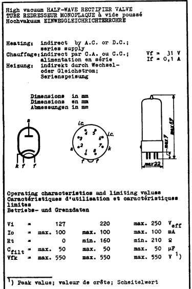
UY41 Specs
The UY41 is a half wave rectifier valve, with a 31V, 100mA heater with a maximum heater / cathode voltage of 550V.
Solid State Equivalents
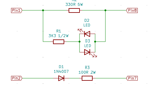
This valve is commonly used in a transformerless configuration, where the heater voltage drop is critical to the circuit functioning. This means that we need to duplicate this 31V / 100mA heater effect; a 330R 5W resistor is fine for this (330R at 100mA is 3.3W).
A 1N4007 diode (1000V peak) is more than adequate to do the rectification.
However, unlike solid state diodes, vacuum rectifiers don't deliver full voltage immediately on switch on, they take a little time to warm up. This means that a solid state diode would deliver a large inrush current into the main filter capacitor which is normally connected to the cathode. Adding a 100R 2W resistor is enough to limit this, especially if the filter cap has been replaced with a modern higher spec one.
This is all we need, but I wanted a visual indication that the power was on, and it's nice to see valves glowing! To give a soft warm glow a red and a yellow LED were wired up back to back (to protect from excessive reverse voltage) and fed through a 3K3 resistor to limit the current to around 8mA. Keeping the current this low allows us to use a ½W resistor here (P = I^2 x R = 211mW).
I was tempted to use a capacitive dropper for the LEDs, but the UY41 can be used with DC, which obviously rules this out.
This gives us the following schematic for the solid state version:
Preparing the Glass Tube
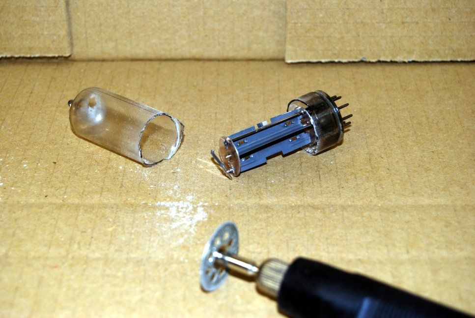
The valve tube was cut with a diamond slitting saw.
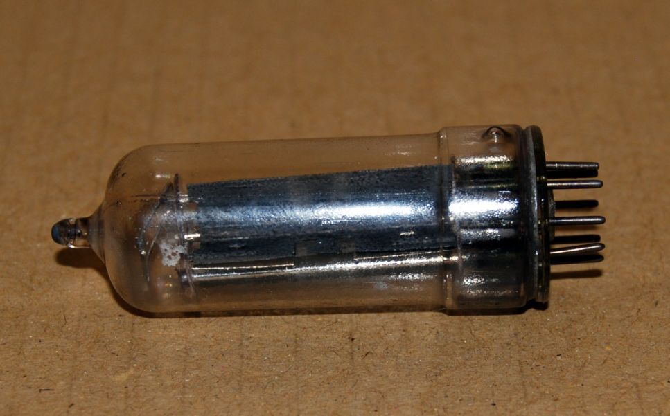
I attempted to cut around the waist where the wider rimlock base meets the narrower main tube. This was mainly successful, but not perfect. More practice needed!
Soldering to the Pins
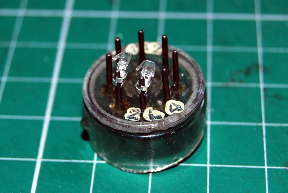
Ok, this was a complete exercise in futility! I could not get any wires to attach, even with a 60W iron.
After much swearing I realised that the single wire crimp connectors used in PCB sockets might fit the valve's pins. The picture below shows a test of a couple of such crimp connections on the outside. They were crimped into place on the inside and enabled the components to be soldered to them. Some attempt to solder them to the pins, along with the epoxy added later, keeps things in place.
Assembly
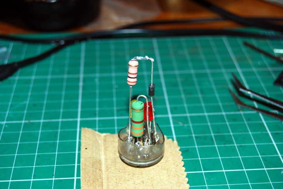
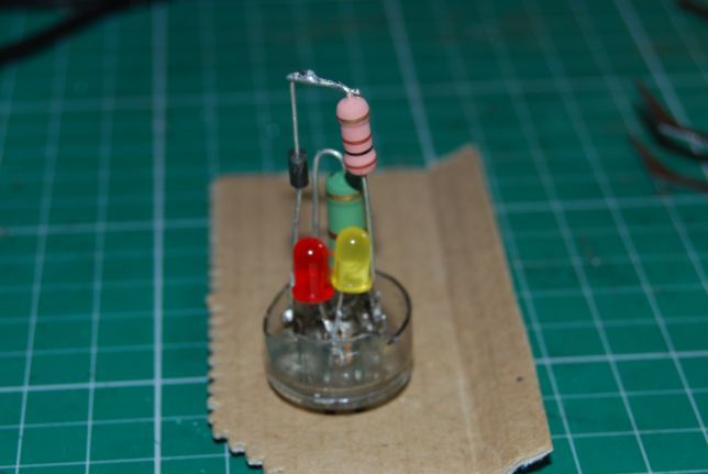
The trickiest part was working out the order of assembly to allow all the components to reside in the tube with no risk of short circuiting.
The LEDs were placed low down, which gives a nice effect when the valve is running, and the other components given lots of space, this was deliberate to give the final device a steampunk type look.
Finishing Off
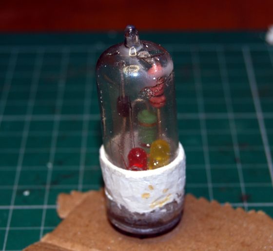
I was hoping to be able to only use clear epoxy to join the tube back up again, thus preserving its original look. Unfortunately my cut wasn't clean and there were some gaps around the glass.
The epoxy held the glass together, but it didn't look too robust. I used a product called milliput, which is an expoxy based filler that hardens almost like ceramic (it can be sanded, tapped, etc.) to make a collar around the join and this works fine. The look isn't quite what I was going for, but it's ok.
If there's a next time I'll take more care to finish off the cut more neatly. This would result in less height in the valve, but should allow just epoxy to seal it. I was too hurried this time!
Testing
Before using the new "valve" it needs to be tested to make sure the connections are where we want them and that there are no shorts.
Pins 1 and 8 should show just under 330 ohms and neither pin should connect to any other pin on the valve.
Pins 2 and 7 should show a diode drop plus a little (due to the resistor) with +ve connected to pin 2 and -ve to pin 7. This was around 0.64V on my valve. Swapping the polarity of the connections should show an open circuit. Neither pin should connect to any other pin on the valve.
All the other pins should be isolated from each other.
Pins 1 and 8 were connected to a variable (DC) power supply and the voltage wound up to 31V. The current should be very close to 100mA at 31V and one of the LEDs should light. Swapping the polarity should light up the other LED. With AC both LEDs are on at the same time.
In Use
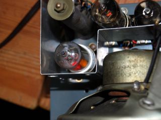
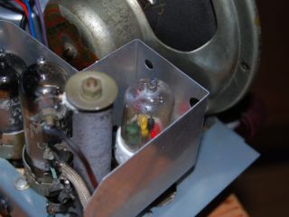
The gallery pictures below show the solid state valve in situ in my Murphy U198 receiver along with some larger copies of the construction images.


