Musical Fidelity Elektra E10 Amplifier Repair
My trusty Musical Fidelity Elektra E10 amplifier decided it was in a huff. Rather than spend £150 just to have it looked at I decided to investigate myself. The hardest part turned out to be taking the thing apart!
tl;dr; A capacitor in the PSU had failed.
The Problem
The right hand channel failed on powering the amp up.
A quick swap of the speaker cables showed it wasn't the speaker at fault. Careful listening showed that there was a very slight sound which had a "shooshing" feel to it coming from the speaker.
I had a gut feel that this was a power supply issue, but nothing beyond that. So time to open it up.
Getting Access to the Circuit Board
This turned out to be pretty involved. I've listed all the steps here, mainly for my own reference in case I have to do this again.
Removing the Cover
A torx security screwdriver bit is required to open case. Remove all the screws on the sides and back that hold the top on.
Removing the Front Facia
Control Knobs
This is complicated due to the LEDs inside the volume and input selector knobs. These LEDs are hard wired and held in place by cable grips. The knobs are held in place by grub screws accessible from the rear (see arrow on picture).
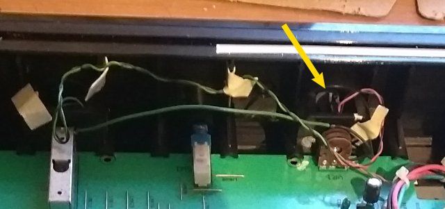
Use a 1.3mm hex key to loosen the grub screws on the volume and input selector controls.
The cable ties used to secure the LEDs to the control's hubs need to be cut off and replaced when re-assembling the amp. The knobs can now be removed.
Note that the volume control has its hole for the LED 180 degrees opposed to the grub screw, while the selector knob has the hole at 90 degrees to the grub screw.
Releasing the Facia
The volume control pot is held onto the facia by a nut which needs to be removed.
Unscrew the three self-tapping screws on underside of the chasis front to release the facia.
The facia then slides off.
Brittle Plastic
The plastic that the facia is made of was quite brittle and had shattered around one of its screw mounts. I used contact adhesive and paper backing to re-assemble the broken plastic.
First Look at the Board
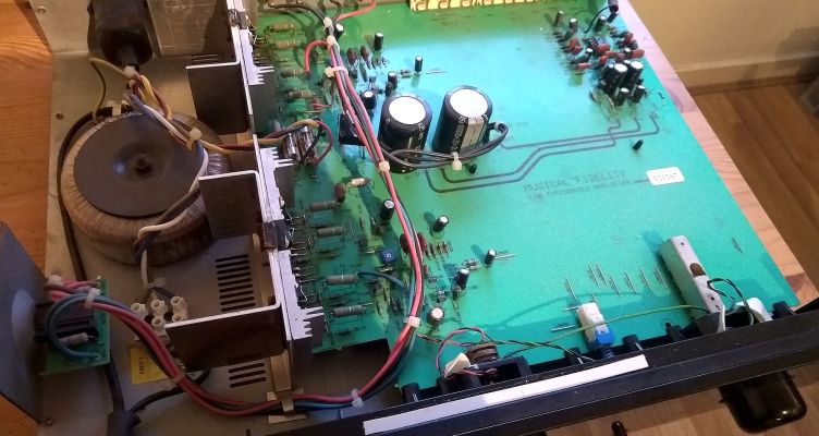
The main image at the top of this page is a general view of the opened amplifier and I've marked up the copy below to help orientate you with the board's layout.
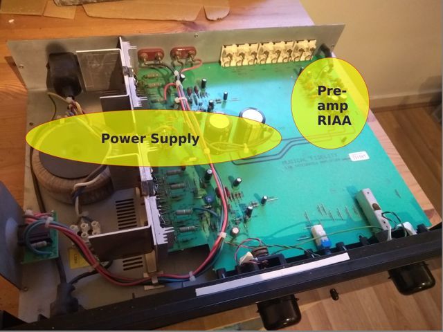
The power supply consists of the transformer, at the left, with leads going to fuses on the PCB, through a bridge rectifier then onto the two large smoothing capacitors at the right.
The fuses were quickly checked and found to be fine.
Then we turn to the 10,000µF smoothing capacitors...
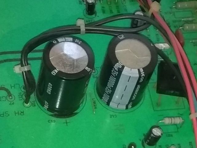
The tops of the capacitors are supposed to the flat, the one on the right is, but you can see in the picture that the left hand one looks deformed. It's a bit tricky to photograph it, but it is very clearly domed up.
This machine is 25 years old (I bought it new in 1995) and it looks like it's using standard capacitors. Capacitors are vulnerable to ageing and eventually failing, heat exacerbates this and this amplifier runs quite hot. Just take a look at the scorching on the PCB at the foot of the power transistors!
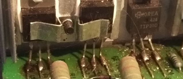
The damaged capacitor is for the right hand power amplifier, so there's a good chance this is what's causing the problem. Given the damage to it I decided to replace it (and it's companion) with some better quality new ones. I didn't even bother testing them before ordering the replacements.
I found some nichicon caps which will do just fine - if you're doing this make sure your replacements have the same, or higher operating voltage than the ones you're replacing.
Releasing the PCB
Now the tricky part; actually getting access to the underside of the PCB to desolder the capacitors.
I won't take you through the trial and error phase, but I decided not to desolder any leads if at all possible. The following steps allow you to free the board and turn it over for soldering.
Release the Heat Sink and Headphone Socket
There are two self-tapping screws on the underside of the chasis that hold the heat sink in place, remove them.
Remove the nut holding the headphone socket in place and free the socket from the chasis.
The transformer is connected to the on/off switch with a connector block, this block needs to be able to move to let you lift the PCB, so remove the two screws holding the connector block to the chasis.
Disconnect the Rear Phono Sockets
The phono sockets on the rear need to be unscrewed from the chasis. Remove the five screws holding them in place.
Lift the Board
The PCB is held down with two plastic posts which have sprung barbs above the board. Squeeze the barbs together while lifting the board and you'll eventually be able to lift it clear of the posts.
The board can now be pivoted up to 90° to the chasis, as shown below.

If you're comfortable working this way then fine, but I'd rather the board was lying flat. This involved:
- Unscrew the on/off switch (two screws)
- Use an 8mm hex socket to unscrew the nut holding the transformer down and lift the transformer off its bolt.
You can now turn the PCB upside down.
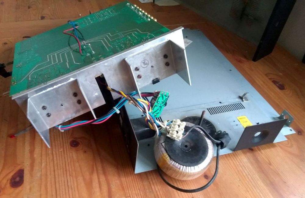
Nice star ground on the board!
Replace the Capacitors
The smoothing capacitors can now be desoldered and replaced.
And Finally...
That was it, a quick test showed the problem had gone away. So that was a good result.
Simply follow the strip down instructions in reverse to put the amplifier back together again. You will need two small cable ties to re-attach the LEDs on the control knobs.
I'm going to have a separate write up on testing the capacitors, this will link to it when it's done.
Why didn't I fully re-cap the amplifier? To be honest I simply had too many other things to do!
Parts
Please consider using the affiliate links below when searching for parts.
It won't cost you any more, and all income from such purchases goes directly to the FIP & FCOV Clinic which carries out treatment and research into the feline coronavirus and the fatal FIP infection that it can cause in cats.
